
Compact FBM240. Redundant with Readback, Discrete
Output and Discrete Input Module

Overview
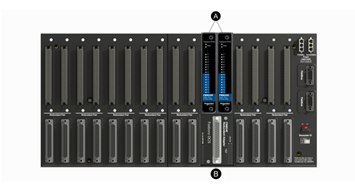
The Compact FBM240is an 8 channel input and 8 channel output Foxboro™ DCS
Fieldbus Module (FBM) available as a single or redundant module. A redundant pair
of the modules combine to provide redundancy at the FBM level, with field I/O wired to
one commontermination assembly (see Figure 1). Each module independently holds
the output(s) at its specified output value(s), and each independently reads back its
observed value of the output.
This module is part of the Compact 200 Series I/O subsystem described in Compact
200 Series I/O Subsystem Overview (PSS 41H-2COV).
Aredundant contact output block in the control software validates each output in
conjunction with information to/from the module.
Features
• Eight discrete outputs/Eight discrete voltage monitor inputs
• Eight discrete inputs read back the voltage across the relay contacts. Sets the
channel BAD if the state of the contact disagrees with the state of the
corresponding output channel
• Monitors each FBMoutput and sets the output channel BAD if the output is in the
wrong state
• Single or redundant module
• Termination Assemblies (TAs) for locally or remotely connecting field wiring to the
Compact FBM240
• Supports discrete relay outputs capable of switching:
◦ 10Aat80to120VAC,or
◦ 5Aat80to125VDC,or
◦ 5Aat15to30VDC,or
◦ 5Aat80to120VAC
• Supports channel-isolated discrete I/O:
◦ 15-60VDC@2A,fusedoutputs
◦ 15-60VDCinputs
NOTE: Support for this termination assembly and the new Fail-Safe
configuration options described in Fail-Safe, page 6 require version 1.40N or
later firmware.
• Redundantoperation failure detection
◦ Outputcontact monitor readback and high coverage of internal FBM detected
failures allows redundant partner to automatically continue to drive discrete
outputs and to monitor inputs
• Internal per channel output demand state failure detection
◦ OutputChannel is marked BAD in both Single and Redundant Operation if the
demand state read-back indicates a state of miss-compare
Internal Readback of Output
The Compact FBM240has8internal readback channels, one per each output
channel, used to verify that the output has changed to the requested state. These
channels read the voltage across the relay contacts on the relay termination
assemblies. The states of these channels are displayed on LEDs on the front panel of
the Compact FBM240. When external power is applied to the relay contact of each
channel, the LED for that channel is ON when the relay contact is CLOSED, and OFF
when the relay contact is OPEN. If the state of the contact disagrees with the state of
the corresponding output channel, the channel is marked BAD.
The FBMalso monitors each of its eight outputs and sets the corresponding output
channel BAD if the output is in the wrong state.
If the channel or input power is marked BAD, the CP presents that information to the
Foxboro DCS for display as a System Management alarm and as a control block
alarm
Redundant Outputs
Aredundant contact output function block, COUTR, is used for each redundant pair of
outputs. The COUTR block handles output writes and initialization logic for the
redundant channels. On each write of the COUTR block, identical output writes are
sent to both modules, fully exercising the Fieldbus and the logic circuitry of each
module. You can select a sustained output that follows the block input or a pulsed
output with a selectable pulse width.
Whenafailure is detected in one of the modules, its output is marked BAD and the
corresponding channel in the good module automatically continues to drive the
discrete outputs.
Each output channel drives an externally powered load. Power for each Compact
FBM240module is diode OR’d together in the redundant adapter to help assure
redundant power. The microprocessor of each module executes the digital output
application program, plus diagnostic routines that validate the health of the FBM.
Fail-Safe
Configurable options for output safety include:
• Digital Output Fail-Safe Fallback Data- specifies the channel fallback value (0 or
1) for each of the eight digital outputs
• Maskoption- determines which of the eight digital outputs hold its current value
and which outputs assume the fallback values
• Fieldbus Fail-Safe Delay Time- length of time the FBM waits for a communication
from the CP before entering a communications fail
Redundant Modules
For redundant modules, the Fail-Safe Fallback Data and mask options are
configurable. An additional option is provided so that the module data will fall back to
zero (0) when the module is put off-line for maintenance functions so that it will not
interfere with the remaining module which is still on-line.
The Compact FBM240requires version 1.40N or later firmware to support this feature.
Single Modules
For single modules, the Fail-Safe Fallback Data and Mask options are configurable.
Compact Design
The Compact FBM240’s design is narrower than the standard 200 Series FBMs. It
has a rugged Acrylonitrile Butadiene Styrene (ABS) exterior for physical protection of
the circuits. Enclosures specially designed for mounting the FBMs provide various
levels of environmental protection, up to G3 harsh environments, per ISA Standard
S71.04.
High Reliability
The redundancy of the module pair, coupled with the high coverage of detected faults,
provides a very high subsystem availability time.
The module performs signal conversion required to interface electrical input signals
from field sensors to the optionally redundant Fieldbus. It executes the Discrete I/O
program with the following configurable options: Input Filter Time, Fail-Safe
Configuration, and Sustained or Momentary Outputs. If the Momentary Output
configuration is selected, then Pulse Output Interval is also configurable.
Whenredundant, either module may be replaced without upsetting field input or
output signals to the good module. The module can be removed/replaced without
removing field device termination cabling, power, or communications cabling
Easy Removal/Replacement
The module mounts on a Compact 200 Series baseplate. Two screws on the FBM
help secure the module to the baseplate.
Redundant modules must be located in adjacent positions on the baseplate, with the
first module located in an odd-numbered position (for example, the positions labelled
“3” and “4”). To achieve redundancy, a redundant adapter module is placed on the two
adjacent baseplate termination cable connectors to provide termination for a single
cable (see Figure 1). A single termination cable connects from the redundant adapter
to the associated termination assembly (TA).
Whenredundant, either module may be replaced without upsetting field input signals
to the good module. Each module can be removed/replaced without removing field
termination cabling, power, or communications cabling.
Modular Baseplate Mounting
The Compact FBM240module mounts on a DINrail mounted Modular Baseplate,
which accommodates up to four or eight FBMs. The Modular Baseplate is either DIN
rail mounted or rack mounted, and includes signal connectors for the redundant
Module Fieldbus, redundant independent DC power, and termination cables.
Redundant modules must be located in odd and even adjacent positions on the
baseplate (positions 1 and 2. 3 and 4. 5 and 6. or 7 and 8). To achieve the
redundancy, a redundant adapter module is placed on the two adjacent baseplate
termination cable connectors to provide a single termination cable connection (See
Figure 1. page 3).
To system configurator applications and to other systems monitoring through SMON,
Foxboro DCS System Manager, and SMDH, redundant FBM240s appear to be
separate, nonredundant modules. The functional redundancy for these modules is
provided by their associated control blocks.
Redundant Modules in Foxboro DCS HMI
The redundant pair of modules appear as two independent modules to system
management software applications (such as Foxboro DCS System Manager and
Termination Assemblies
Field I/O signals connect to the FBM subsystem via DIN rail mounted termination
assemblies (TAs). The TAs used with the Compact FBM240 provide:
• Outputsignal connection points
• External power connection point
• 5Aunsealedrelay or a 10 Aunsealed relay for each output
• 15-60VDCswitch andvoltage monitor inputs
The relay TAs have a high voltage input circuit that monitors the voltage across the
contacts of each output relay. Monitor circuits are located on daughter card
assemblies mounted on the TAs. There are two daughter cards per TA, each with four
monitor circuits. The TAs are:
• RH917YF-80to125VDCat5Aor80to120VACat10A
• RH917HU-80to120VACat5A
• RH926SZ-15to30VDCat5A
• RH916AQ/RH916AR-15to60VDCvoltagemonitor and 2 Aswitch
NOTE: WhentheCompact FBM240output opens, the TA contacts still apply
current to the circuit due to the TA’s readback circuitry, as described in Table 2 and
Table 3.
The RH916AQ/ARpassive TA provides fused 2 A outputs and independent inputs for
use with 15-60 VDC.
The redundant adapter connects the redundant FBM’s baseplate connectors together.
The redundant adapter provides a single termination connection to a single TA.
The DIN rail mounted termination assemblies connect to the redundant adapter by
means of a removable termination cable. The cable is available in a variety of lengths,
up to 30 meters (98 feet), allowing the termination assemblies to be mounted as
needed by plant design.
Visual Indicators
Red andgreen light-emitting diodes (LEDs) incorporated into the front of the modules
provide visual status indications of FBM functions, as well as the discrete states of the
individual output points


Copyright © 2009 - 2014 CHS Automation Technology Co., Ltd. (K&J) All Rights Reserved
CHS Automation (K&J) has been deeply involved in the field of industrial automation for many years, focusing on providing highly reliable industrial control core components and system support for shipbuilding, shipping, and marine engineering.